Showing posts with label Sensors. Show all posts

Sunday, May 9, 2021

LDR (Light Dependent Resister): Explained.


Light Dependent Resistor (LDR) :


            In this blog, we're going to be talking about a light-dependent resistor otherwise known as the LDR or a photoresistor. There are many different types of photoresistors but they will generally have some kind of look. The clue as to what they do is reflected in its name. It is a resistor that is light-dependent and what that means is that this is a resistor that changes its resistance depending on the amount of light that hits it.

Constituents:

They are made from a semiconductor material so that when light hits the semiconductor material it becomes more conductive and therefore has less resistance. If we attach this LDR with a multi-meter so we will be measuring the resistance across it. If we are in the kilo-ohms range, you can see that this resistor will have a resistance of 2-kilo ohms. If we give light to it, we will notice that its resistance drops below the range of the multimeter. So if we adjust the range of the multimeter, we can see now that the resistor has a resistance of under 1-kilo ohm. As we will move the light-dependent resistor closer and closer to the light source, we will notice that the resistance drops and as we will pull it away from the light source, the resistance starts to increase again. Now as we cover the LDR, we will return again to the 2-kilo ohms range of the multi-meter. Now if we cover this LDR, we will notice that the resistance will climb up to over 150 kilos. This is very high resistance. The darker the environment that this LDR experiences, the higher its resistance becomes.

Practical Uses of LDR:

Now we have covered that what an LDR is and the basic principle of how they work you may be asking what are the practical uses of LDRs and how can they be used within a circuit. Well LDRs or light-dependent resistors are generally used in applications where light is an important factor to the device it's being used in need to know when its light or dark outside so that they know when to turn on and when to turn off. They are also used as light meters in cameras. They can also be used as the light detector for an alarm, night lights, and many other things basically if we need to control something with light then an LDR is one of the most common ways that we can do that.


Hope that this article will cover the LDR.

Stay tuned as more interesting things are coming.

Bye.


Saturday, May 8, 2021

Ultrasonic Sensor: Explained.


Ultrasonic Sensor:


            An ultrasonic sensor is a sensor that emits ultrasonic waves and detects the object that is in front of it with the help of the waves.

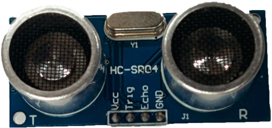
There are different types of ultrasonic sensors. But HC-SR04 sensor is the main focus here as it is very common for Arduino projects. The detail of this sensor is as follows:

Transmitter and Receiver:

            When we see an HC-SR04 Sensor, there are two speakers like things. But their functionality is not the same. These are basically transmitter and receiver. The left one is a transmitter that generates ultrasonic waves. And the receiver receives these waves.

Working:

            As I stated above, the transmitter generates the waves and the receiver receives them. When the waves are generated and sent out, the sensor notices their time and if the receiver receives these waves according to calculations i.e. according to the expected time, there is nothing in front of the sensor. And when these waves are not received according to the calculations i.e. they are received before the expected time, there is some object in front of the sensor. These sensors are cheap and are very accurate.

Pins:

            The first pin on the left side is the VCC pin which is connected to the positive of the 5v power supply. The next two pins are Trig and Echo pins which are responsible for the output of information that the sensor records. And the last pin is the GND pin which is connected to the negative side of the supply.

Range:

            The range of this sensor is as far as 3 meters. We can adjust the range by changing the figure into the code of Arduino as they are commonly used with Arduinos.

Tasks:

            Many tasks can be performed by this sensor. Such as measuring small distances, we also can place them at the door with a buzzer so we can know that someone has entered the room. We can use it as obstacle avoiding feature for our robots, cars, etc. We can do many other things as well.


Hope that this article will clear your concept.

Stay tuned.

Bye.

Tuesday, May 4, 2021

Infrared Sensor: Explained.


Infrared (IR) Sensor:

In this blog, I am going to explain IR sensors. First, we will see its structure, and then we will see it working. So let’s begin.

Structure:

          If you see the picture above, this is a very common type of IR sensor. There are more types as well. But this type is the main focus here.

Working of LEDs:

This sensor consists of a white LED as well as a Black Led. One LED sends signals while the other one receives them.

Range:

The range of this sensor is not very long. It is usually about 10-12 cm.

Potentiometer:

 When you see on the top of it, you will notice a blue potentiometer from which its range can be adjusted by rotating the screw-type


thing with a screwdriver.

Lights:

There are two lights next to the potentiometer. One light is to display that the module is powered on while the other is to show that this sensor is detecting something. Its working is not very difficult.

Pins:

There are three pins next to the lights. The first pin is OUT. This pin sends signals to the component connected to it. Next to it, there is a GND pin which is negative. Next to it, the VCC pic is a positive pin where we can give 5v from Arduino or any other power supply.

Scanners: Explained.

 Introduction:           If you need a copy of a document that is sitting on your table. For this, with your PC, you use your flatbed scan...