Showing posts with label For Beginners. Show all posts

Monday, May 31, 2021

Voltage Regulators: Explained.

Introduction:

    In the world of electronic circuit design, the selection of the right voltage regulator is one of the most important decisions. Virtually, every product that runs on DC power employs voltage regulation.


Voltage Regulators:

    Athe name indicates, voltage regulators take a variable or unstable input voltages and convert them to higher or lower constant output. That matches the voltage and current needs of an electronic circuit. Basic regulators of the linear IC type regulators simply drop down the source to the desired level and shed the rest as heat while the others such as the switching type are more efficient. Simply stated, rapidly switching a voltage input on and off results in an averaged voltage output, depending upon switching frequency. A wide range of voltages is possible from a single source. Some regulators employ additional features to handle large voltage spikes, reverse polarity protection, or remove unwanted signal noise, automotive alternators.

For use in electrical systems and charging the vehicle's battery, most alternators employ a built-in AC to DC rectifier and a robust voltage regulator that is capable of delivering 13.5 to 14.5 volts DC above 100 amps. Each device in the electrical system may have its own voltage regulator depending on its specific needs. Common voltages are 12 volts DC for lighting and accessories and 5 volts DC for sensors and control modules. 


Types:

Linear regulators use a transistor that is controlled by feedback from a differential amplifier circuit and a reference voltage to control the output voltage. They may feature fixed or adjustable output. Output current is determined by the input current minus circuit operation losses. Linear regulators are simple to add and give a fast response time but are not very efficient. The output of a linear regulator is always lower than the input and drops out if the input voltage is too low. 

Switching regulators are very efficient but can be difficult to design. As mentioned, earlier switching regulators use controllers to rapidly connect and disconnect either the positive or negative component of the source voltage from the rest of the converter circuit to produce desirable changes in voltage and current. A feedback loop from the output to the controller helps to determine the switching rate. The arrangement of inductors, capacitors, and diodes in basic switching converters determines if the output voltage is increased or decreased.

Buck-boost converters can increase or decrease voltage but

reverse the polarity.
Fly-back transformers increase the voltage to 
very high levels but at very low current by collapsing the field of an energized coil much like the ignition system in some
automobiles.


These are the basic functionality, types, and common
applications of voltage regulators. 


Stay tuned. Bye.


Monday, May 24, 2021

Buzzers: Explained.


Buzzer


Introduction:

            A buzzer is a small yet efficient component that adds sound features like buzzing or beeping sound to various projects which are implemented. It is a very small and compact two-pin structure and can be easily used on breadboards. It also acts as an indicator that makes this widely used component. It is actually an audio signaling device that is integrated with electronic transducers.

Structure:

            Internally, the buzzer consists of a Piezo Element which we will discuss later. Let’s discuss the pin configuration of a buzzer. A buzzer is a two-pin sensor. It has only two terminals that are a positive terminal and a negative terminal. The positive terminal is actually a longer terminal and is powered to the input voltage and the negative terminal is the short terminal and which is typically connected to the ground of the system.


Types:

            Let's discuss the types of Buzzers. There are two types of Buzzers. One is an active buzzer and the other is a passive buzzer. Active buzzer consists of an internal oscillator that helps the Buzzer to make the beep sound and it requires only DC voltage as input.

Passive buzzer acts like electromagnetic speakers where whenever there is a change in input, it produces sound. It requires an AC signal to produce a sound.

Working of a Buzzer:

            Let's just understand the construction and working of a buzzer. At the heart of all Piezo-type buzzers, is a piezoelectric element. This piezoelectric element is composed of a piezoelectric ceramic and a metal plate which is held together with adhesive, this metal plate is also known as a vibration plate. Both sides of the ceramic plate contain an electrode which is used for electrical conduction purpose. The piezoelectric materials exhibit a specific phenomenon, known as the piezoelectric effect and reverse piezoelectric effect. When this is exposed to the mechanical strain, it will cause the material to develop an electric field and vice-versa, where these piezoelectric plates are in turn connected to the positive and negative terminals of the Buzzer. When an alternating voltage is applied to Piezo ceramic element, the element expands and contracts diametrically. This characteristic of piezoelectric material is utilized to make the ceramic plate vibrate rapidly, which generates sound waves.

Applications:

            We hear buzzers in our daily life like alarm system, then calling Bell, then washing machine where washing machine finishes its operation and the buzzer beeps. Next is the timer cycle has completed so whenever a timer cycle will complete, the buzzer beeps and indicates the operation.


Stay tuned.

BYE.

Tuesday, May 18, 2021

Bread Boards: Explained.


Bread Boards:


                Breadboards are used to prototype circuits. If you've got a starter kit with your Arduino or Raspberry Pi you probably have one. They come in many sizes for the most part the standard large size and slightly smaller size. The bigger bread boards have lines running all the way down the longest side which are known as the power rails. This is because you can plug your microcontroller or power supply into them to provide power to the components. On the inside running perpendicular to these are the component lines and these are where you place your components. This is where you can build your circuit. Smaller bread boards work exactly the same as the larger ones though they don't have the power rails running down. On each side by flipping over a breadboard and pulling off the backing, you can see how they work. These pieces of metal run all the way along the board and connect all of the components together that you need. If you were to pull out one of the metal lines on your breadboard, you will see that there are all small metal crimps that are designed to grab the legs of the components. This is why they're so useful. It means you can make circuits without having to rely on learning how to solder or using a soldering iron and it's very easy to prototype things quickly. One of the feature of the breadboard that you'll see is that down the middle there is a channel and this channel is a specific size and for a specific reason. The reason is that it's there is because many integrated circuits or chips comply to a standard called dual inline packages. For example, if we have an l293d motor IC that is designed for driving motors in a circuit, it fits perfectly over that little channel.

                You're wondering why this plastic device that you have that helps you make circuits is called a breadboard. It harks back to the history of DIY electronics when people also wanted to prototype quick circuits but they didn't want to have to get soldering iron out or anything like that. What they would do is they'd get an actual breadboard from their kitchen and they would use that with their components along with some screws or some nails or some thumbtacks to make quick circuits just to test things out or learn about electronics. So that is in brief what a breadboard is and what you can use one for.


Stay tuned.

Bye.

Tuesday, May 11, 2021

7 Segment Display: Explained.


7 Segment Displays:


7-segment displays are a fun component to use in Arduino projects. You can use them to track time or keep score in a game. In this article, we'll discuss that how they work.


First, take a look at the seven segments. Each of these is labeled with a letter A to G. Each letter is then associated with a unique pin on the four-digit display. In addition, each of the four digits of the display has a pin associated with it. The remaining pin on the component is for the decimal point. To create the correct digit on the display, the correct pins must be turned on. For example, to create the number two in the second digit, we'd need to turn on pin D2 then we'd also need to turn on pins. A B D E and G technically the display is not capable of displaying more than one digit at a time however there are obviously times when we'd like to see more than one digit on the display to do this. We'll use the phenomenon of persistence of vision to trick our eyes and brains into seeing multiple digits. While the display will only show one digit at a time, we can insert a very short delay before the next digit appears. This will trick our eyes and brains into seeing the digits at the same time using delays as short as 5 milliseconds or 5 thousandths of a second will enable us to see 4 digits at a time.

Now that you know how the four-digit 7 segment displays works.


I hope that this article will help you.

Stay tuned.

Bye.


Monday, May 10, 2021

Solar inverter Explained with its types.


Solar Inverter:


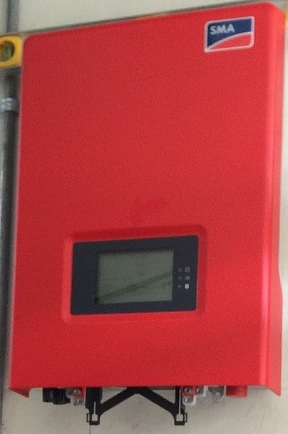
            A solar inverter is a device that converts the DC electricity received from your solar panels into a form of electricity that can be used by appliances and other electronics in your home. Let's understand how it works and the different types of inverter available for solar panels.

During the day when the sun shines on the solar panels installed in your homes, electrons within the solar cells start to move around which produces DC energy. The energy then goes straight into the inverter which converts it into AC energy which is the standard electrical current used to power appliances at home.

Now we know how the solar inverter works.


Kinds and their Functions:

            Let's look at the various kinds and their functions. There are three co-types of the solar inverter which is: grid-tie inverters, off-grid inverters, and hybrid inverters.


Grid Tie inverters: Grid-tie inverters are used with the solar PV system that is integrally connected to the utility grid power. They must connect to the grid to function the electricity produced by the solar system which is not consumed in the property is automatically injected into the grid via a bi-directional meter. In case of the power is cut, the inverter stops to function as a safety feature which is known as anti-eye landing. This system doesn't have a battery backup. So during a power cut, you will not have access to power. Hence this system can be used in areas where there are rare or very few power cuts. It can alternatively be used if you have a normal inverter battery system at home for power backup during the power cut off.


Off-Grid inverters: Off-Grid inverters on the other hand work just like the normal inverters used at home. In this system, DC power generated by a solar panel is used to charge the solar battery. When there is a power cut, the inverter will draw stowed energy from the battery converting DC power from the battery to usable AC power for running electrical appliances. This system can be used in areas where there is a frequent or long power cut.


Hybrid inverter: Combining the capabilities of both grid-tied and off-grid inverters into one, a hybrid inverter system can be used in both high power cut areas or areas where there is a rare or very little power cut. Under normal operating conditions, it can supply power to the home, charge the batteries and excess power can be fed into the grid.

In case of a power cut, the unit will automatically switch over to battery supply and continue to operate independently from the electricity grid.


I hope that this article will cover the topic of inverters.

Stay tuned.

Bye.


Scanners: Explained.

 Introduction:           If you need a copy of a document that is sitting on your table. For this, with your PC, you use your flatbed scan...